DSI Mining Canada
Mining
See Mining products

|
||||||||||||||||||||||||||||||
|
||||||||||||||||||||||||
|
||||||||||||||||||||||||

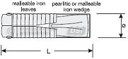 Expansion Shells
• for 5/8" & 3/4" UNC threads & 7/8" where applicable
• Ø = 1-1/32" (26 mm) hole size: model F1F, L = 3-1/4"
• Ø = 1-1/4" (32 mm) hole size: model F1-1/4B, L = 3-1/4"
• Ø = 1-3/8" (35 mm) hole size: model F2B, L = 2-7/8"
• Ø = 1-1/2" (38 mm) hole size: model D1L, L = 5"
• Ø = 1- 3/4" (45 mm) hole size: model D5-1, L = 3"
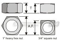
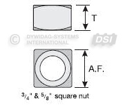 Nuts
Nuts
• for TBE rock bolts only
• for 5/8" and 3/4" & 7/8" UNC thread:
• A.F. = 1-1/8" square
• T = 0.8"
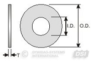 Hardened Round Washers
• to ASTM F436 specifications
• for 5/8" and 3/4" thread
• I.D. = 13/16"
• O.D. = 1-15/32"
• T = 0.122" to 0.177"
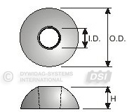 Spherical Seat (Compensation) Washers
• ductile iron ASTM A536 Gr. 65-45-12
• for 5/8” thread:
• I.D. = 11/16”, O.D. = 2”, H = 3/4” (model TSW-2)
• I.D. = 15/16”, O.D. = 2”, H = 1/2” (model TSW)
• for 3/4” thread:
• I.D. = 13/16”, O.D. = 2”, H = 13/16” (model TSW-4)
• I.D. = 15/16”, O.D. = 2”, H = 1/2” (model TSW)
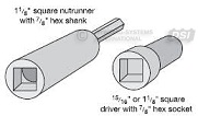 Installation Tools - for stopers/jacklegs
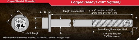
• for forged head rockbolts:
• 1-1/8" square driver
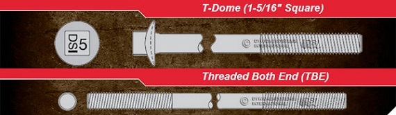
• 15/16" square driver (for T-Dome bolts)
• for TBE bolts:
• 1-1/8" square nutrunner
• available with 7/8" hex shank or socket
Rope thread and T-thread drivers and nutrunners available on request.

 Expansion Shells
• for 3/4” thread (model F1-1/4B):
• L = 3-1/4”
• Ø = 1-1/4” (32 mm) hole size
• for 1 thread (model F9F):
• L = 3-1/4"
• Ø = 1-3/4"
Nuts
• for 3/4” thread: A.F. = 1-1/8” square; T = 0.8”
• for 1” thread: A.F. = 1-5/8” hex; T = 63/64”
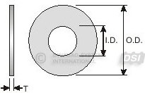 Hardened Round Washers
• to ASTM F436 specifications
• for 3/4” thread:
• I.D. = 13/16”, O.D. = 1-15/32”, T = 0.122” to 0.177”
• for 1” thread:
• I.D. = 1-1/8”, O.D. = 2”, T = 0.136” to 0.177”
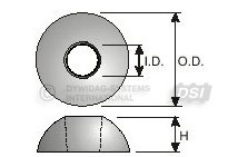 Spherical Seat (Compensation) Washers
• ductile iron ASTM A536 Gr. 65-45-12
• for 3/4" thread:
• I.D. = 13/16”, O.D. = 2”, H = 13/16” (model TSW-4)
• I.D. = 15/16”, O.D. = 2”, H = 1/2” (model TSW)
• for 1” thread: I.D. = 1-1/16”, O.D. = 2”, H = 1/2” (model TSW-1)
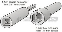 Installation Tools - for stopers/jacklegs
• 1-1/8” square nutrunner (for 3/4” bolts)
• 1-5/8” hex nutrunner (for 1” bolts)
• available with 7/8” hex socket or 3-1/4” long 7/8” hex shank
Rope thread and T-thread drivers and nutrunners available on request.

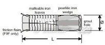
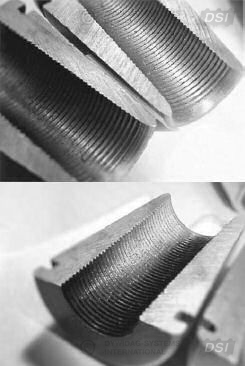 The anchorage of most cable bolts consists of a wedge barrel and a 2- or 3-part wedge. The wedge segments grip the cable by means of tooth shaped threads which are forced into the surface of the cable wires.
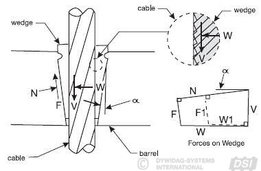
Warning: If friction increases (due to corrosion), a larger F will reduce the clamping force. As V increases, all other forces can only increase if the wedge can seat deeper into the barrel. If the wedge is restrained to do so (i.e. by corrosion or dirt accumulation), the clamping force can not increase with the pulling force causing slippage when the load on the cable bolt gradually increases during service life.
To avoid slippages during use, it is important that the cable bolt is fully stressed at time of installation to a force equal to 0.5 Fu. (ie. 50% of the capacity of the cable)
The clamping force W is highly dependent on the friction between wedge and wedge hole. For normal friction conditions, the clamping force W is more than 4 times the cable pulling force V and it adjusts with the pulling force V.
When a wedge is properly seated, radial cracks may develop indicating adequate seating.
The wedge can be supplied with a rubber O-ring or a metal spring ring holding the wedge segments together.