Power-Duct™ Non-Segregated Phase Bus Duct
Data:
Standard Construction
|
Rating |
Amperes (A) |
Bottom |
Sides |
Top |
Conductors |
Support |
|
600 V |
1,200 A |
Steel |
Steel |
Steel |
One 1/4" x 4 cu |
1/2" GPO-3 sheet |
|
600 V |
1,600 A |
Steel |
Steel |
Steel |
Two 1/4" x 4 cu |
1/2" GPO-3 sheet |
|
600 V |
2,000 A |
Steel |
Steel |
Steel |
Two 1/2" x 4 cu |
1/2" GPO-3 sheet |
|
600 V |
3,200 A |
Aluminum |
Aluminum |
Aluminum |
Two 1/2" x 6 cu |
1/2" GPO-3 sheet |
|
600 V |
4,000 A |
Aluminum |
Aluminum |
Aluminum |
Two 5/8" x 6 cu |
1/2" GPO-3 sheet |
|
5 kV |
1,200 A ND |
Steel |
Steel |
Steel |
One 1/2" x 4 cu |
Molded |
|
5 kV |
1,200 A |
Steel |
Steel |
Steel |
One 1/4" x 6 cu |
Molded |
|
5 kV |
2,000 A |
Steel |
Steel |
Steel |
One 1/2" x 6 cu |
Molded |
|
5 kV |
3,000 A |
Aluminum |
Aluminum |
Aluminum |
Two 1/2" x 6 cu |
Molded |
|
15 kV |
1,200 A |
Steel |
Steel |
Steel |
One 1/4" x 6 cu |
Molded |
|
15 kV |
2,000 A |
Steel |
Steel |
Steel |
One 1/2" x 6 cu |
Molded |
|
15 kV |
3,000 A |
Aluminum |
Aluminum |
Aluminum |
Two 1/2" x 6 cu |
Molded |
 |
 |
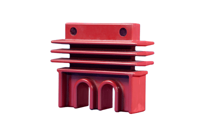
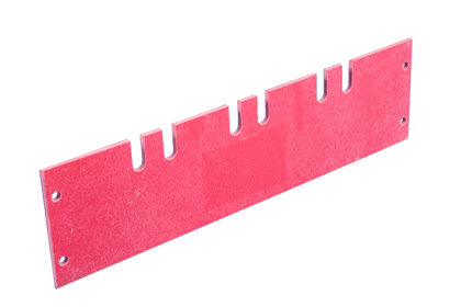
| 5 kV and 15 kV Molded Support | 600 V 1/2" GPO-3 Sheet |
Specification
Bus
1. The conductors shall be 99 percent plus conductivity copper with silver-plated joints capable of carrying rated current continuously without exceeding a temperature rise of 65 °C based on a 40 °C ambient temperature.
2. The copper bars shall be mounted on track-resistant material. For 2.4 kV service and above, the copper bars shall be insulated with an epoxy coating.
3. Conductors shall be braced to withstand fault currents as indicated on contract drawings.
4. Typical joints shall be insulated with removable boots and jointed by double splice plates. Atypical joints may use tape or heat-shrink tubing to insulate when insulation is required.
5. A 0.25" x 2.0" bare copper ground bus shall be supplied and bolted to each metal enclosure to provide continuous electrical ground when adjacent enclosures are connected together to minimize the possibility of circulating currents.
Enclosures
1. All enclosures shall be 11-gauge steel, aluminum or stainless steel.
2. Enclosures shall have bolted, removable covers.
Wiring/terminations
1. Manufacturer shall provide an external two-hole ground pad at each end for ground connections or connect the ground bus in the enclosure to the ground bus in the terminating equipment.
Finish
1. The exterior finish of the enclosure shall consist of one coat of ANSI-61 gray baked-on, polyester powder paint. The paint will be applied electrostatically to pre-cleaned, phosphatized steel. The finish will have corrosion resistance of 600 hours to five percent salt spray.
Miscellaneous
1. Expansion joints, equipment terminations, wall flanges and vapor barriers shall be provided as indicated on contract drawing.
2. Space heaters shall be applied either to the entire bus or the outdoor section of the bus according to manufacturer recommendations. The 250 V or 500 V rated heaters shall be applied at 120 V or 240 V for longer life.
a. The heaters shall be controlled by [thermostat] [continually energized].
b. The heater connections shall [be wired for connections to terminal blocks in terminating equipment] [provide junction box with terminal strip for purchaser’s AC connection].
3. Support
a. Indoor enclosures shall be designed to be a combination of [hung from overhead by hangers] [supported from below by structural supports] [trapeze supports].
b. Outdoor enclosures shall be supported from below by structural steel.
c. Manufacturer shall supply mounting provisions and supply all necessary information to the contractor for supporting equipment design.
d. All overhead hanger rods and bottom steel supports shall be supplied and installed by the contractor as required by the manufacturer.